
Robot is an electromechanical device which can react in some way to its environment, and take autonomous decisions or action...

Different types of motors
Robot is an electromechanical device which can react in some way to its environment and take autonomous decisions or actions to achieve a specific task.
Roboticists develop man-made mechanical devices that can move by themselves, whose motion must be modelled, planned, sensed, actuated, and controlled, and whose motion behavior can be influenced by “programming”.
This definition implies that a device can only be called a “robot” if it contains a movable mechanism, influenced by sensing, planning, actuation and control components. Motors and actuators are the devices which make the robot movable. Motors and actuators convert electrical energy into physical motion. Most actuators produce either rotational or linear motion.
In this article I will explain more common types of motors and actuators, their basics and how to control them.
Step 1: Types of Motors

1 / 6 • Servo motor
You already know that electric motors are used to “actuate” something in your robot: its wheels, legs, tracks, arms, fingers, sensor turrets, camera, or weapon systems. There are literally dozens of types of electric motors, but I will discuss the most common types used in amateur robotics. Motors are classified as:
AC motor
Brushed DC motor
Brushless DC motor
Geared DC motor
Servo motor
Stepper motor
DC Linear Actuator
AC (alternating current) motors are rarely used in mobile robots because most of the robots are powered with direct current (DC) coming from batteries. Also, since electronic components use DC, it is more convenient to have the same type of power supply for the actuators as well. AC motors are mainly used in industrial environments where very high torque is required, or where the motors are connected to the mains / wall outlet. So, I will not explain about AC motors here.
Step 2: Motor Controller

1 / 5 • Motor controller
A motor controller is an electronic device that helps microcontroller to control the motor. Motor controller acts as an intermediate device between a microcontroller, a power supply or batteries, and the motors.
Although the microcontroller (the robot’s brain) decides the speed and direction of the motors, it cannot drive them directly because of its very limited power (current and voltage) output. The motor controller, on the other hand, can provide the current at the required voltage but cannot decide how the motor should run.
Thus, the microcontroller and the motor controller must work together in order to make the motors move appropriately. Usually, the microcontroller can instruct the motor controller on how to power the motors via a standard and simple communication method such as UART or PWM. Also, some motor controllers can be manually controlled by an analogue voltage (usually created with a potentiometer).
The physical size and weight of a motor controller can vary significantly, from a device smaller than the tip of your finger used to control a mini sumo robot to a large controller weighing several Kg. The size of a motor controller is usually related to the maximum current it can provide. Larger current means larger size.
Since there are several types of motors, there are several types of motor controllers (different type of motor requires different type of controller) :
Brushed DC motor controllers: used with brushed DC, DC gear motors, and many linear actuators.
Brushless DC motor controllers: used with brushless DC motors.
Servo Motor Controllers: used for hobby servo motors.
Stepper Motor Controllers: used with unipolar or bipolar stepper motors depending on their kind.
Step 3: Brushed DC Motor

1 / 6 • Internal structure of DC motor
A brushed DC motor is one which uses two brushes to conduct current from source to armature. There are several variations on the brush DC motor, but permanent magnet DC motor (PMDC) is used extensively in robotics. Brushed DC motors are widely used in applications ranging from toys to push-button adjustable car seats. Brushed DC (BDC) motors are inexpensive, easy to drive, and are readily available in all sizes and shapes.
The brush DC Motor consists of six different components: the axle, armature/rotor, commutator, stator, magnets, and brushes. A Brush DC Motor consists of two magnets facing the same direction, that surrounding two coils of wire that reside in the middle of the Brush DC Motor, around a rotor. The coils are positioned to face the magnets, causing electricity to flow to them. This generates a magnetic field, which ultimately pushes the coils away from the magnets they are facing and causes the rotor to turn.
The Brush DC Motor has two terminals; when voltage is applied across the two terminals, a proportional speed is outputted to the shaft of the Brush DC Motor. A Brush DC Motor consists of two pieces: the stator which includes the housing, permanent magnets, and brushes, and the rotor, which consists of the output shaft, windings, and commutator. The Brush DC Motor stator is stationary, while the rotor rotates with respect to the Brush DC Motor stator. The stator generates a stationary magnetic field that surrounds the rotor. The rotor, also called the armature, is made up of one or more windings. When these windings are energized, they produce a magnetic field. The magnetic poles of this rotor field will be attracted to the opposite poles generated by the stator, causing the rotor to turn. As the motor turns, the windings are constantly being energized in a different sequence so that the magnetic poles generated by the rotor do not overrun the poles generated in the stator. This switching of the field in the rotor windings is called commutation.
Unlike other electric motor types (i.e., brushless DC, AC induction), BDC motors do not require a controller to switch current in the motor windings. Instead, the commutation of the windings of a BDC motor is done mechanically. A segmented copper sleeve, called a commutator, resides on the axle of a BDC motor. As the motor turns, carbon brushes slide over the commutator, encountering different segments of the commutator. The segments are attached to different rotor windings; therefore, a dynamic magnetic field is generated inside the motor when a voltage is applied across the brushes of the motor. It is important to note that the brushes and commutator are the parts of a BDC motor that are most prone to wear because they are sliding past each other.
Applications:
Toys
RC Servos
Gear Motors
Advantages:
Inexpensive
Lightweight
Reasonably Efficient
Good low-speed torque
Limitations: In addition to the audible whine from the commutator brushes, these motors create a lot of electrical noise which can find its way back into other circuitry and cause problems.
Visit for DC motor: //www.sparkfun.com/categories/247
Step 4: Controlling of Brushed DC Motor

1 / 9 • Motor controller circuit using 555timer
By the term controlling I mean both direction control and the speed control. The direction of the DC motor can be reverse by simply reversing the polarity of the battery connection. The speed of the motor can be control by changing the voltage level and dc voltage level can be changed by PWM signal. For higher voltage level speed will be higher and for lower voltage level speed will also be lower.
Practically, Drive circuits are used in applications where a controller of some kind is being used and speed control is required. The purpose of a drive circuit is to give the controller a way to vary the current in the windings of the BDC motor. The drive circuits discussed in this section allow the controller to pulse width modulate the voltage supplied to a BDC motor. It is more efficient way to vary the speed of a BDC motor compared to traditional analog control methods. In some cases, the motor only needs to spin in one direction then a single switch topology with PWM modulation can be used to vary the voltage applied to the motor and thus to control its speed. The higher the PWM duty cycle, the faster the motor will go. Figure shows circuit for driving a BDC motor in one direction using single FET (field effect transistor).

Simple motor controller using transistor
Note that in the circuit there is a diode across the motor. This diode is there to prevent Back Electromagnon- nitic Flux (BEMF) voltage from harming the MOSFET. BEMF is generated when the motor is spinning. When the MOSFET is turned off, the winding in the motor is still charged at this point and will produce reverse current flow. D1 must be rated appropriately so that it will dissipate this current.
Resistors R1 and R2 in the Figure are important to the operation of the circuit. R1 protects the microcontroller from current spikes while R2 ensures that transistor is turned off when the input pin is tristate.
When positioning is required or when both directions of rotation are needed (most robots need) a full H-bridge with PWM control is used. The H-Bridge is a 4-transistor circuit that allows you to reverse the current flow to the motor. With an H-Bridge and a PWM pin, you can control both the speed and direction of the motor.
To understand please follow the next step.
Step 5: H Bridge

1 / 6 • H-bridge IC
A H bridge is an electronic circuit that enables a voltage to be applied across a load in either direction. These circuits are often used in robotics and other applications to allow DC motors to run forwards and backwards.
An H-bridge is a transistor-based circuit capable of driving motors both clockwise and counter-clockwise. It’s an incredibly popular circuit – the driving force behind countless robots that must be able to move both forward and backward. Fundamentally, an H-bridge is a combination of four transistors with two inputs lines and two outputs:(Note: there’s usually quite a bit more to a well-designed H-bridge including flyback diodes, base resistors, and Schmidt triggers.)
To understand this, the H-bridge must be broken into its two sides, or half-bridges. Referring to Q1 and Q2 make up one half-bridge while Q3 and Q4 make up the other half-bridge.

4 transistor H-bridge
Each of these half-bridges can switch one side of the BDC motor to the potential of the supply voltage or ground. When Q1 is turned on and Q2 is off, for instance, the left side of the motor will be at the potential of the supply voltage. Turning on Q4 and leaving Q3 off will ground the opposite side of the motor. The switching elements (Q1.Q4) are usually bi-polar or FET transistors, in some high-voltage applications IGBTs.
Note the diodes across each of the transistor (D1-D4). These diodes protect the transistors from current spikes generated by BEMF when the transistors are switched off. The top-end of the bridge is connected to a power supply (battery for example) and the bottom-end is grounded.
A capacitor can be used with parallel to the diode. But it is optional. The value of these capacitors is generally in the 10-pF range. The purpose of these capacitors is to reduce the RF radiation that is produced by the arching of the commutators.

Forward direction switching
The basic operating mode of an H-bridge is simple: if Q1 and Q4 are turned on, the left lead of the motor will be connected to the power supply, while the right lead is connected to ground. Current starts flowing through the motor which energizes the motor in (let’s say) the forward direction and the motor shaft starts spinning.
..............................................................................................................

Reverse direction switching
If Q2 and Q3 are turned on, the reverse will happen, the motor gets energized in the reverse direction, and the shaft will start spinning backwards.
.............................................................................................................................................................................................

Wrong switching
In a bridge, you should never ever close both Q1 and Q2 (or Q3 and Q4) at the same time. If you did that, you just have created a low-resistance path between power and GND, effectively short-circuiting your power supply. This condition is called ‘shoot-through’ and is an almost guaranteed way to quickly destroy your bridge, or something else in your circuit.
There are many different models and brands of H-Bridge IC is available. Most used are Texas Instruments L293NE or a Texas Instruments SN754410 and L298 from STMicroelectronics.
L293D
The L293NE/SN754410 is a very basic H-bridge. It has two bridges, one on the left side of the chip and one on the right and can control 2 motors. It can drive up to 1 amp of current and operate between 4.5V and 36V. The small DC motor generally used in robot bots can run safely off a low voltage so this H-bridge will work just fine.
The H-bridge has the following pins and features:
Pin 1 (1,2EN) enables and disables our motor whether it is giving HIGH or LOW
Pin 2 (1A) is a logic pin for our motor (input is either HIGH or LOW)
Pin 3 (1Y) is for one of the motor terminals
Pin 4-5 are for ground
Pin 6 (2Y) is for the other motor terminal
Pin 7 (2A) is a logic pin for our motor (input is either HIGH or LOW)
Pin 8 (VCC2) is the power supply for our motor, this should be given the rated voltage of your motor
Pin 9-11 are unconnected as you are only using one motor in this lab
Pin 12-13 are for ground
Pin 14-15 are unconnected
Pin 16 (VCC1) is connected to 5V Below is a diagram of the H-bridge and which pins do what in our example.
Included with the diagram is a truth table indicating how the motor will function according to the state of the logic pins (which are set by our Arduino).
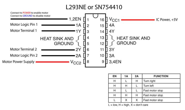
H bridge truth table
Bear in mind that all motors are available in different sizes.
Small motors are engineered for applications where compactness is valued over torque. While there are small high-torque motors, these tend to be expensive because they use rare earth magnets, high efficiency bearings, and other features that add to their cost. Large motors may produce more torque, but also require higher currents. High current motors require larger capacity batteries, and bigger control circuits that won’t overheat and burn out under the load. Therefore, match the size of the motor with the rest of the robot. Don’t overload a small robot with a large motor when big size isn’t important. When decided on the size of the motor, compare available torque after any gear reduction. Gear reduction always increases torque. The increase in torque is proportional to the amount of gear reduction: if the reduction is 3:1, the torque is increased by about three times (but not quite, because of frictional losses).
For H-bridge IC and module please visit:
//www.sparkfun.com/search/products?term=h%20...
Step 6: Arduino DC Motor Control
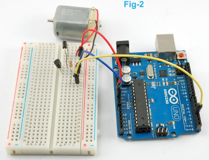
1 / 9 • Arduino DC motor control
As you already know DC motor must not connect directly to Arduino pin because it can burn your Arduino. So, you must connect a transistor between Arduino and motor. Let's first control a small DC motor using single transistor. Using single transistor, you know only speed can be control. PWM is used to control speed of a DC motor. Connect your circuit as Figure-1. Arduino PWM pin must be connected to the base pin of transistor.
See code snippet #1
Now, connect the motor using H-Bridge IC (I used L293 here). Follow Fig-3 & Fig-4. We can control both speed and direction now. Pin 9 is used as PWM pin and a switch is added to control the speed.
See code snippet #2
L293 is a dual H bridge IC. So, you can control two motor by single IC. Connect two motor to the IC as like figure 5 and use the following code. Make modification according to your requirement.
See code snippet #3
.
Step 7: DC Gear Motor

1 / 2 • Geared motor
Geared DC motors can be defined as an extension of DC motor which already had its Insight details demystified before. A geared DC Motor has a gear assembly attached to the motor. The speed of motor is counted in terms of rotations of the shaft per minute and is termed as RPM. The gear assembly helps in increasing the torque and reducing the speed. Using the correct combination of gears in a gear motor, its speed can be reduced to any desirable figure. This concept where gears reduce the speed of the vehicle but increase its torque is known as gear reduction. This Insight will explore all the minor and major details that make the gear head and hence the working of geared DC motor.
Working of the DC Geared Motor
The DC motor works over a fair range of voltage. The higher the input voltage more is the RPM (rotations per minute) of the motor. For example, if the motor works in the range of 6-12V, it will have the least RPM at 6V and maximum at 12 V. In terms of voltage, we can put the equation as: RPM= K1 * V, where K1= induced voltage constant V=voltage applied.
The working of the gears is very interesting to know. It can be explained by the principle of conservation of angular momentum. The gear having smaller radius will cover more RPM than the one with larger radius. However, the larger gear will give more torque to the smaller gear than vice versa. The comparison of angular velocity between input gear (the one that transfers energy) to output gear gives the gear ratio. When multiple gears are connected, conservation of energy is also followed. The direction in which the other gear rotates is always the opposite of the gear adjacent to it. In any DC motor, RPM and torque are inversely proportional. Hence the gear having more torque will provide a lesser RPM and converse. In a geared DC motor, the concept of pulse width modulation is applied.
For example, an unloaded DC motor might spin at 12000 rpm and provide 0.1 kg-cm of torque. A 225:1 geardown is added to proportionally reduce the speed and increase the torque: 12000 rpm / 225 = 53.3 rpm and 0.1 x 225 = 22.5 kg-cm. The motor will now be able to move significantly more weight at a more reasonable speed.
In a geared DC motor, the gear connecting the motor and the gear head is quite small, hence it transfers more speed to the larger teeth part of the gear head and makes it rotate. The larger part of the gear further turns the smaller duplex part. The small duplex part receives the torque but not the speed from its predecessor which it transfers to larger part of other gear and so on. The third gear’s duplex part has more teeth than others and hence it transfers more torque to the gear that is connected to the shaft.
Controlling of Geared Motor
DC gear motor can be controlled the same way DC motor control.
Applications:
Robot Drive Trains
Radio Control Vehicles
Cordless Tools
Advantages:
Speed Reduction - Many DC motors simply run too fast to be useful in direct-drive applications.
Increased Torque - A lot of work can be coaxed from a relatively small motor if fitted with a suitable gear train.
Limitations: This is especially a problem with low-cost plastic gear trains used with low-voltage motors. The extra resistance can make these gear-trains balky at low speeds.
For Controller & Motor browse: www.sparkfun.com
Step 8: Brushless DC Motor

1 / 8 • ESC of brushless DC motor
Brushless DC (BLDC) motors are called by many names: brushless permanent magnet, permanent magnet ac motors, permanent magnet synchronous motors etc. The confusion arises because a brushless dc motor does not directly operate from a dc voltage source. However, as we shall see, the basic principle of operation is like a dc motor.
A BLDC has a rotor with permanent magnets and a stator with windings. It is essentially a dc motor turned inside out. The brushes and commutator have been eliminated and the windings are connected to the control electronics. The control electronics replace the function of the commutator and energize the proper winding. As shown in the animation, the winding is energized in a pattern which rotates around the stator. The energized stator winding leads the rotor magnet, and switches just as the rotor aligns with the stator. There are no sparks, which is one advantage of the BLDC motor.
The brushes of a dc motor have several limitations: brush life, brush residue, maximum speed, and electrical noise. BLDC motors are potentially cleaner, faster, more efficient, less noisy, and more reliable. However, the BLDC motor requires electronic control.
Then the construction of a brushless DC motor is very similar to the AC motor making it a true synchronous motor, but one disadvantage is that it is more expensive than an equivalent “brushed” motor design.
In runner’s vs Outrunners
There are two types of Brushless RC motors, in runners and outrunners.
The permanent magnets of in runner brushless motors are positioned on the inside of the electromagnets. An outrunner brushless motor has the permanent magnets on the outside of the electromagnets.
The faster a motor spins, the more efficient it is. In runner motors turn very fast and are much more efficient than outrunner motors. In runner Brushless RC Motors require a speed reducing gearbox between the motor and propeller of your RC airplane.
The downside of an in runner is the added parts that can and do fail. The gears get stripped, and the gearbox shafts are easily bent. It can also be an obstacle when mounting the gearbox motor combination for your RC airplane neatly, especially under a cowling.
Theory of Operation
The mechanics of a brushless motor are incredibly simple. The only moving part is the rotor, which contains the magnets. Where things become complicated is orchestrating the sequence of energizing windings. The polarity of each winding is controlled by the direction of current flow. The animation demonstrates a simple pattern that controllers would follow. Alternating current changes, the polarity, giving each winding a “push/pull” effect. The trick is keeping this pattern in sync with the speed of the rotor. There are two (widely used) ways this can be accomplished. Most hobby controllers measure the voltage produced (back EMI) on the un-energized winding. This method is very reliable in high velocity operation. As the motor rotates slower, the voltage produced becomes more difficult to measure and more errors are induced. Newer hobby controllers and many industrial controllers utilize Hall effect sensors to measure the magnets position directly. This is the primary method for controlling computer fans.
Operation of brushless motor
Control
The control of the brushless DC motors is very different from the normal brushed DC motor, in that it this type of motor incorporates some means to detect the rotors angular position (or magnetic poles) required to produce the feedback signals required to control the semiconductor switching devices. The most common position/pole sensor is the “Hall Effect Sensor”, but some motors also use optical sensors. Using Hall effect sensors, the polarity of the electromagnets is switched by the motor control drive circuitry. Then the motor can be easily synchronized to a digital clock signal, providing precise speed control. Brushless DC motors can be constructed to have, an external permanent magnet rotor and an internal electromagnet stator or an internal permanent magnet rotor and an external electromagnet stator.

Timing diagram of brushless motor
In figure 4 (A), the GREEN winding labeled “001” is energized as the NORTH pole and the BLUE winding labeled as “010” is energized as the SOUTH pole. Because of this excitation, the SOUTH pole of the rotor aligns with the GREEN winding and the NORTH pole aligns with the RED winding labeled “100”. To move the rotor, the “RED” and “BLUE” windings are energized in the direction shown in figure 4(B). This causes the RED winding to become the NORTH pole and the BLUE winding to become the SOUTH pole. This shifting of the magnetic field in the stator produces torque because of the development of repulsion (Red winding – NORTH-NORTH alignment) and attraction forces (BLUE winding – NORTH-SOUTH alignment), which moves the rotor in the clockwise direction.
Speed Control
Brushless dc motor are three phase ac motors. To control the speed an electronic speed control or ESC is used. Brushless ESC systems basically create a tri-phase AC power output of limited voltage from an onboard DC power input, to run brushless motors by sending a sequence of AC signals generated from the ESC's circuitry, employing a very low impedance for rotation. Brushless motors, otherwise called outrunners or in runners depending on their physical configuration, have become very popular with "electro flight" radio-control aeromodelling hobbyists because of their efficiency, power, longevity and light weight in comparison to traditional brushed motors. However, brushless AC motor controllers are much more complicated than brushed motor controllers.
The correct phase varies with the motor rotation, which is to be considered by the ESC: Usually, back EMF from the motor is used to detect this rotation, but variations exist that use magnetic (Hall Effect) or optical detectors. Computer-programmable speed controls generally have user-specified options which allow setting low voltage cut-off limits, timing, acceleration, braking and direction of rotation. Reversing the motor's direction may also be accomplished by switching any two of the three leads from the ESC to the motor.
Current Rating of Esan ESC will have a power limit. To handle more power, the ESC needs to be larger, heavier, and is more expensive. It’s important to know the peak current your motor is going to pull at full throttle. This determines the current rating you should look for in an ESC. Always choose an ESC with a current rating that is higher than what you need. If the motor is going to pull 12A, a 25A-rated ESC is a much better choice than a 10A-rated one. The 10A ESC will probably overheat and cook, even if you only fly at half throttle. ESCs are relatively light and maintain great resale value, so this is one item in your power system where skimping isn’t worthwhile. Choosing the correct type and identifying the minimum current rating are the two big steps. The next choices depend on your preferences.
Voltage Rating
All ESCs have voltage limits. Some even have more than one! What is your battery voltage? Choose an ESC that is designed to work with an equal or higher voltage. Some ESCs are designed for low voltages (below 13V), some for medium voltages (below 25V), and some for high voltages (above 25V). You shouldn’t connect a high voltage battery to a low voltage ESC, but it is also wasteful to use a high voltage ESC with a low voltage battery.
Advantages
Advantages of the Brushless DC Motor compared to its “brushed” cousin is higher efficiencies, high reliability, low electrical noise, good speed control and more importantly, no brushes or commutator to wear out producing a much higher speed. However, their disadvantage is that they are more expensive and more complicated to control.
Arduino Control
Brushless motors designed for autonomous and remote-control aircraft and vehicles typically require a separate controller. These are typically of the senseless type and use standard servo type pulsed signals for speed control.
Controlling BLDC motor is very easy. Most of the ESCs need a 50Hz frequency i.e., a 20 mms cycle and the speed depend upon the duty cycle you provide. 1ms will reduce its speed to minimum or even stop it (it depends upon the ESC model) while a 2ms pulse will run the motor on its fullest speed. The values between them give you a variation in speed.
Usually, ESCs need a voltage higher than the one provided by the Arduino from his 5V pin: typically they need 2 LiPo cells (around 8V). To achieve that all the circuit must be powered from an external power supply connected directly to the ESC and not via the Arduino, which will be powered by the BEC circuit of the ESC. To make that happen it’s enough to connect the red and black of the control connector to the 5V and GDN of the Arduino board.

Arduino ESC connection
The rest of the circuit is easy: from pin 9 of the Arduino, we have the signal for the ESC, and into pin 0, the voltage reading from the potentiometer comes in.
Sometimes ESC needs calibration and in terms of ESCs, calibration means to set the max and min speeds of the motor in relation to the max and min width of the PWM signal sent by the Arduino. The PWM signal read by the ESC is the same type as a servo signal, meaning the Servo library from Arduino can be used to calibrate and control the ESCs. The ESC sets the speed of the motor depending on the ratio of high to low signals. Calibration involves programming the ESC to understand the PWM waves corresponding to the stop and maximum speeds of the motor.
The default signal range for most servo motors and ESCs is a high signal width between 1000 and 2000 microseconds over a repetition period of 20 milliseconds (assuming a 50hz PWM signal). For the quad copter, however, we want the range to be as wide as possible to allow for greater incremental control of the motor. To this end, we calibrated the ESCs to read a signal width from 700 to 2000 microseconds with 700 being the stop speed and 2000 being the max speed. Some ESC could not read a signal lower than 700 microseconds.
Calibrating the ESCs is quite simple. To enter programming mode, the maximum servo signal (2000 microseconds) is sent to the ESC, the ESC is powered on and waits for two seconds, then the minimum servo signal is sent (700 microseconds). Once the ESC emits a series of confirmation beeps (special wave signals sent to the motor to emit beeping sounds), the ESC is calibrated (check the ESC specific datasheet for details).
See code snippet #4
It just takes the reading of the “throttle”, maps it from 0-1023 to 0-179 (analog reading to servo “degrees”) and then sends it to the ESC via the Servo library. Even in its extreme simplicity this sketch it very useful when you want to calibrate a new ESC to work with the Servo library of Arduino.
Applications:
Multicomputer
Drones
Radio Control Vehicles
Disk Drives
Fans
Industrial Servos
Hybrid Vehicles
High-End Gearmotors
Advantages:
Quiet
Efficient
Limitations: Some types of brushless motors require a separate controller for operation.
For brushless DC motor visit //www.sparkfun.com/categories/245
Step 9: Servo Motor

1 / 6 • Internal structure of servo motor
A servo motor is an electrical device which can push or rotate an object with great precision. If you want to rotate and object at some specific angles or distance, then you use servo motor. It is just made up of simple motor which run through servo mechanism. If motor is used is DC powered then it is called DC servo motor, and if it is AC powered motor then it is called AC servo motor. We can get a very high torque servo motor in a small and light weight packages. Doe to these features they are being used in many applications like toy car, RC helicopters and planes, Robotics, Machine etc. The position of a servo motor is decided by electrical pulse and its circuitry is placed beside the motor.
Now day’s servo system has huge industrial applications. Servo motor applications are also commonly seen in remote controlled toy cars for controlling direction of motion and it is also very commonly used as the motor which moves the tray of a CD or DVD player. Beside these there are other hundreds of servo motor applications we see in our daily life. The main reason behind using a servo is that it provides angular precision, i.e., it will only rotate as much we want and then stop and wait for next signal to take further action. This is unlike a normal electrical motor which starts rotating as and when power is applied to it and the rotation continues until we switch off the power. We cannot control the rotational progress of electrical motor; but we can only control the speed of rotation and can turn it ON and OFF.
Servo Mechanism It consists of three parts:
Controlled device
Output sensor
Feedback system
It is a closed loop system where it uses positive feedback system to control motion and final position of the shaft. Here the device is controlled by a feedback signal generated by comparing output signal and reference input signal.
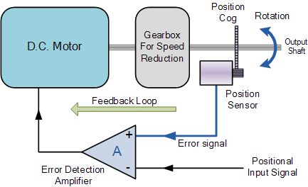
Here reference input signal is compared to reference output signal and the third signal is produces by feedback system. And this third signal acts as input signal to control device. This signal is present if feedback signal is generated or there is difference between reference input signal and reference output signal. So, the main task of servomechanism is to maintain output of a system at desired value at presence of noises.
Working principle of Servo Motors. A servo consists of a Motor (DC or AC), a potentiometer, gear assembly and a controlling circuit. First, we use gear assembly to reduce RPM and to increase torque of motor. Say at initial position of servo motor shaft, the position of the potentiometer knob is such that there is no electrical signal generated at the output port of the potentiometer. Now an electrical signal is given to another input terminal of the error detector amplifier. Now difference between these two signals, one comes from potentiometer and another comes from other source, will be processed in feedback mechanism and output will be provided in term of error signal. This error signal acts as the input for motor and motor starts rotating. Now motor shaft relates to potentiometer and as motor rotates so the potentiometer and it will generate a signal. So as the potentiometer’s angular position changes, its output feedback signal changes. After some time the position of potentiometer reaches at a position that the output of potentiometer is same as external signal provided. At this condition, there will be no output signal from the amplifier to the motor input as there is no difference between external applied signal and the signal generated at potentiometer, and in this situation motor stops rotating.
Controlling Servo Motor:

Servo motor is controlled by PWM (Pulse with Modulation) which is provided by the control wires. There is a minimum pulse, a maximum pulse, and a repetition rate. Servo motor can turn 90 degree from either direction form its neutral position. The servo motor expects to see a pulse every 20 milliseconds (mms) and the length of the pulse will determine how far the motor turns. For example, a 1.5ms pulse will make the motor turn to the 90° position, such as if pulse is shorter than 1.5ms shaft moves to 0° and if it is longer than 1.5ms than it will turn the servo to 180°. Servo motor works on PWM (Pulse width modulation) principle, means its angle of rotation is controlled by the duration of applied pulse to its Control PIN. Basically, servo motor is made up of DC motor which is controlled by a variable resistor (potentiometer) and some gears. High speed force of DC motor is converted into torque by Gears. We know that WORK= FORCE X DISTANCE, in DC motor Force is less and distance (speed) is high and in Servo, force is High, and distance is less. Potentiometer is connected to the output shaft of the Servo, to calculate the angle and stop the DC motor on required angle.
To recap, there are two important differences between the control pulse of the servo motor versus the DC motor. First, on the servo motor, duty cycle (on-time vs. off-time) has no meaning whatsoever—all that matters is the absolute duration of the positive-going pulse, which corresponds to a commanded output position of the servo shaft. Second, the servo has its own power electronics, so very little power flows over the control signal. All power is draw from its power lead, which must be simply hooked up to a high-current source of 5 volts.
Continuous Rotation Servo Motors
Continuous rotation servo motors are a modified version of what the servos are meant to do, that is, control the shaft position. The 360° rotation servos are made by changing certain mechanical connections inside the servo. However, certain manufacturer like parallax sells these servos as well. With the continuous rotation servo, you can only control the direction and speed of the servo, but not the position.
Arduino Servo Control
Servo motors have three wires: power, ground, and signal. The power wire is typically red and should be connected to the 5V pin on the Arduino or Genuine board. The ground wire is typically black or brown and should be connected to a ground pin on the board. The signal pin is typically yellow, orange, or white and should be connected to pin 9 on the board.
Code
See code snippet #5
Applications:
Robotics
Animatronics
Radio Control Cars/Boats/Planes
Advantages:
Low cost - (RC Servos) Smaller sized servos can be purchased for just a few dollars.
Variety - There is a wide range of sizes and torque ratings
Simple to control - using logic level pulses from a microcontroller or a dedicated servo controller
Limitations: Most RC servos are limited to 180 degrees of motion and positioning accuracy and repeatability of +/- 1 degree is typical.
You can find different types of Servo motor at Sparkfun.com
Step 10: Stepper Motor

1 / 5 • Internal structure of Stepper motor